Monday, September 9, 2013

How To Create vSphere Storage DRS Datastore Clusters in 9 Easy Steps

How To Create vSphere Storage DRS Datastore Clusters in 9 Easy Steps

Storage DRS can alleviated the problems associated with VM provisioning and storage environment monitoring. Here are the steps to create them.
Storage DRS is a new feature introduced in vSphere 5.0 that helps in preventing these problems. It provides smart virtual machine placement and load balancing mechanisms based on I/O and space capacity. Storage DRS will help decrease operational effort associated with the provisioning of virtual machines and the monitoring of the storage environment.
The first step to enabling Storage DRS is creating a datastore cluster:


1. From the vCenter Home view, select Datastores and Datastore Clusters.
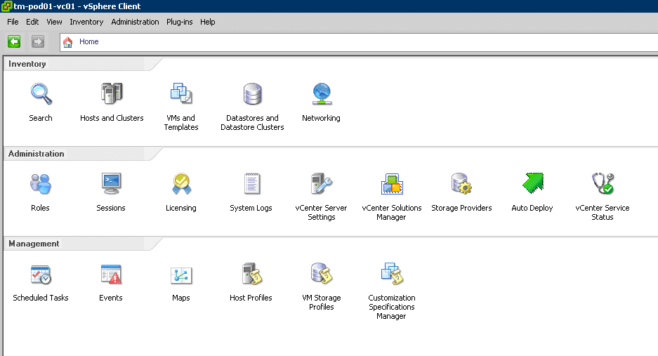
Figure 1. Select Datastores and Datastore Clusters. (Click image to view larger version.)
2. Select your Datacenter object and right click it and select New Datastore Cluster.
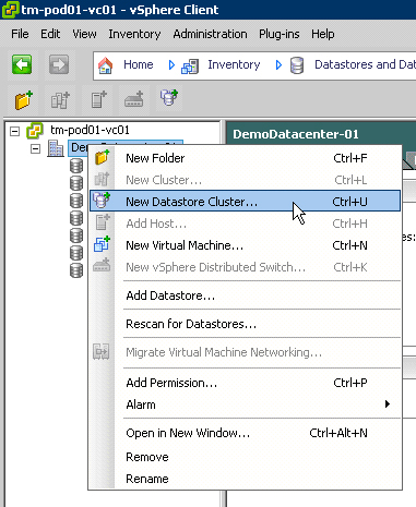
Figure 2. Create a New Datastore Cluster.
3. Give the Datastore Cluster a name and click Next.
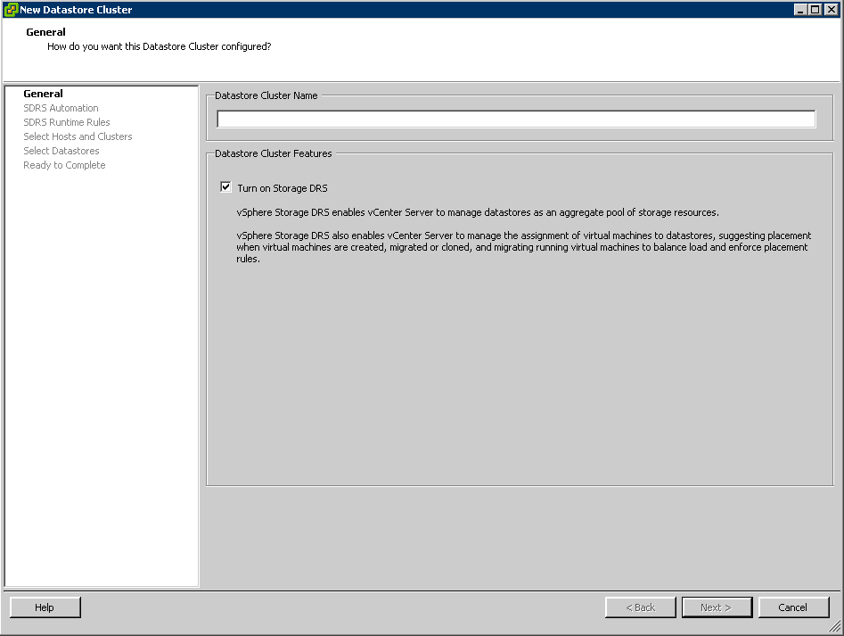
Figure 3. Name your new Datastore Cluster. (Click image to view larger version.)
4. Select No Automation (Manual Mode) and click Next.
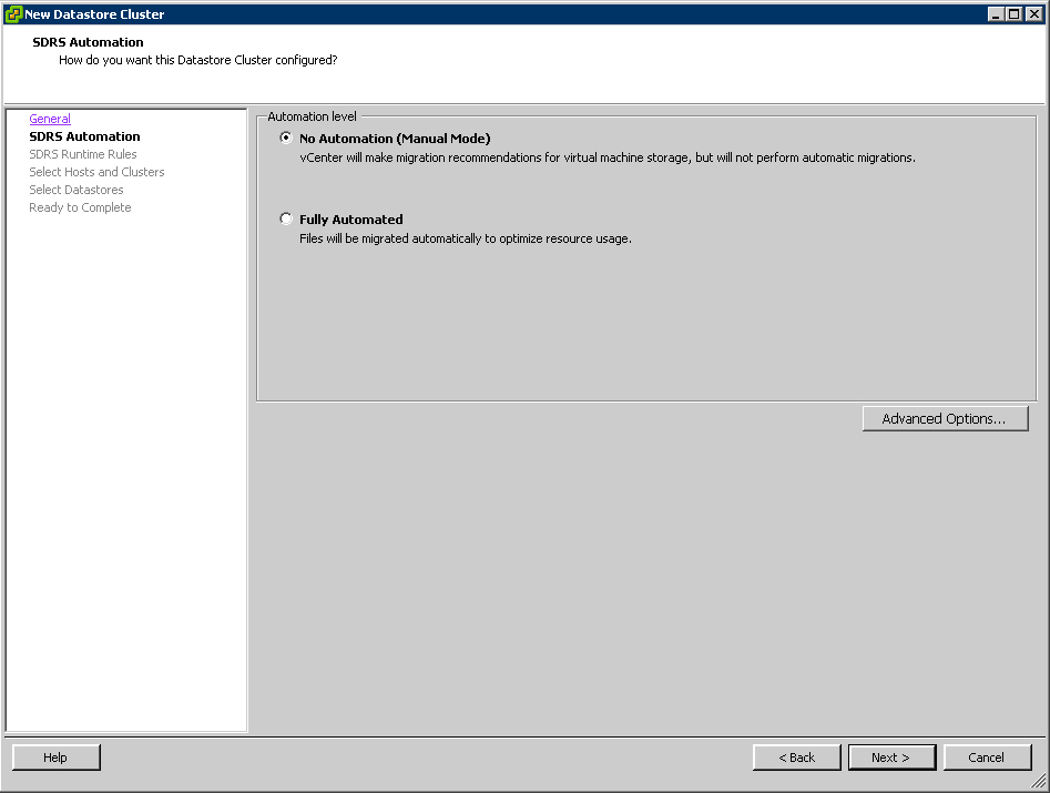
Figure 4. Select the No Automation option. (Click image to view larger version.)
Manual mode means that Storage DRS will only make recommendations and that the user will need to apply these. Fully Automated means that Storage DRS will make recommendations and apply these directly by migrating virtual machines or virtual disks to the proposed destination datastore.
Similar to the early days of DRS, start off with manual mode, review the recommendations provided by Storage DRS and as you start to feel comfortable with the recommendations, consider setting Storage DRS to Fully Automated. Changing this setting can be done any time, providing the ability to switch back and forth.
5. Click on Show Advanced Options.
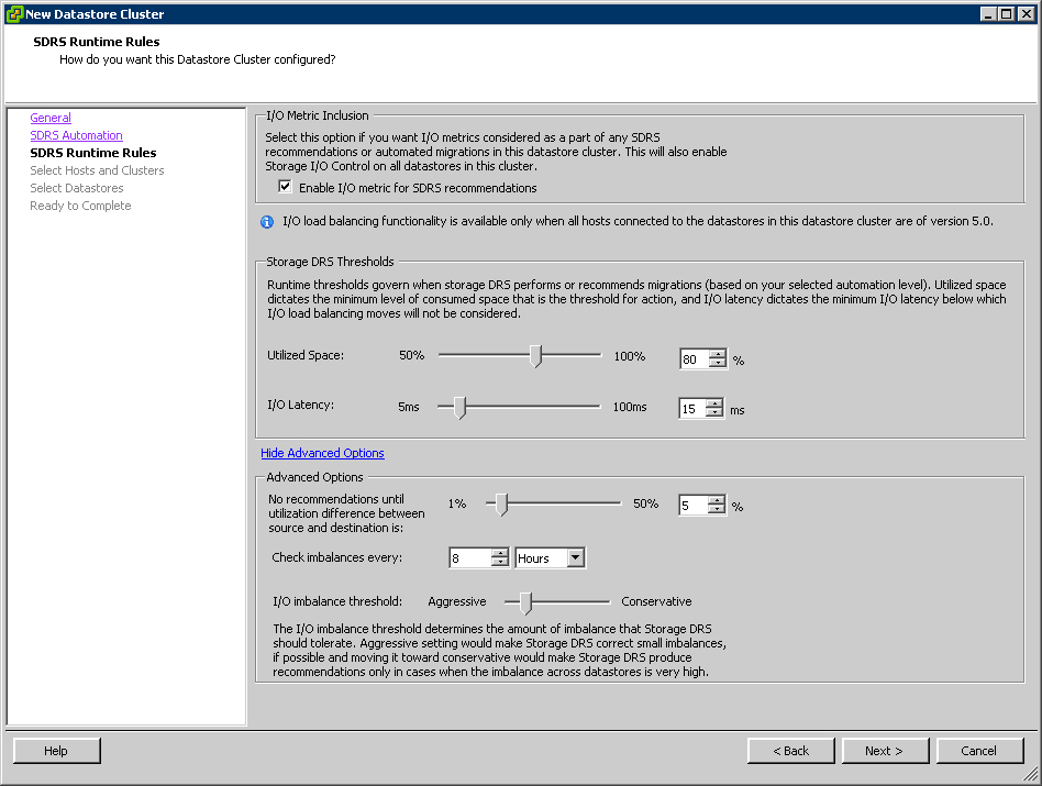
Figure 5. Select Show Advanced Options for more configuration options. (Click image to view larger version.)
The top part of Fig. 5 shows the threshold for both Utilized Space and I/O Latency. Storage DRS will only make recommendations when either of the two are exceeded. At the bottom of the screen you will see the utilization difference, invocation period and the imbalance threshold.

The utilization difference is the minimal difference between the source and the destination. Based on this value, Storage DRS will filter out those datastores whose utilization difference is below the given threshold during the selection of a destination. The default is set to 5%.

The aggressiveness factor determines the amount of I/O imbalance Storage DRS should tolerate. The invocation period, by default 8 hours, determines how often Storage DRS will evaluate the environment and possibly generate recommendations.

Review the space utilization threshold and understand how this percentage will affect storage reserved per datastore. The default recommendation is 20%; however, this might be too much if large datastore sizes are used or too low if small datastores are present. Tuning will depend on how much storage you feel you need to reserve to allow for normal provisioning to take place while you add storage.

6. Review default settings and click Next. Note that Storage DRS enables Storage I/O Control automatically when "I/O Metric" is enabled.


7. Select the cluster to which you want to add this Datastore Cluster.

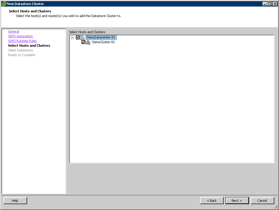
Figure 6. Select a cluster that you'll add to the newly created Datastore Cluster. (Click image to view larger version.)


8. Select the datastores which should be part of this Datastore Cluster.


Figure 7. Now, add datastores. (Click image to view larger version.)


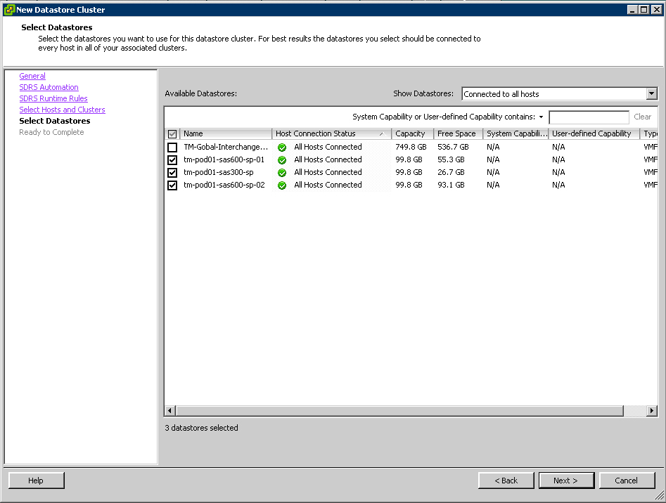
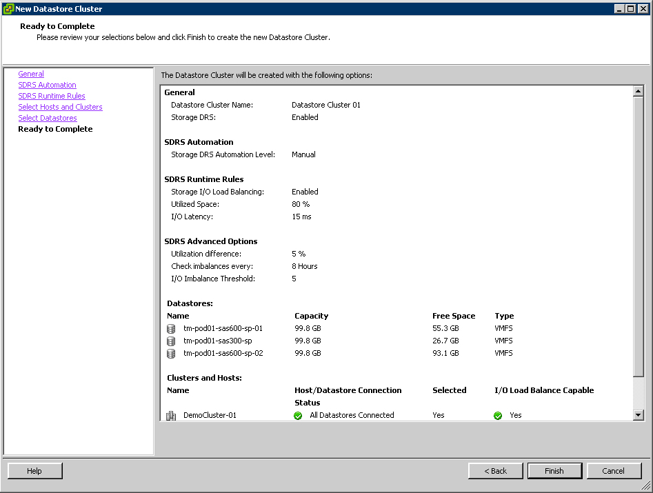
We are using datastores which already contain virtual machines. Creating a datastore cluster is a non-disruptive task and can be done if needed during production hours. Select datastores that are connected to all hosts inside the compute cluster, as this provides the best load balancing options on both compute cluster and datastore cluster levels. The host connection status column helps to identify any current connectivity inconsistencies in your compute cluster.
9. Review your selections, ensure all hosts are connected to the datastores in the datastore cluster and click Finish
Figure 8. Review, then you're done. (Click image to view larger version.)


The datastore cluster will now be created and a new object should appear on the "Datastores and Datastore Clusters" view. This object should contain the selected datastores.


vSphere 5.1 DRS Groups and Rules


  • Creating virtual machine DRS Groups
  • Creating host DRS Groups
  • Creating Run VMs on Hosts Rules
    • Must versus should
  • Creating Separate Virtual Machines/Keep Virtual Machines Together Rules

Creating virtual machine DRS Groups

To create a virtual machine DRS Group:
1. Right-click the DRS cluster in question, then click Edit Settings.
Alternatively, select the DRS cluster in the Hosts and Clusters inventory view, then click Edit Settings.


2. Click DRS Groups Manager under vSphere DRS.

3. Here, you’ll see any existing DRS Groups. Click Add under Virtual Machines DRS Groups to add a new virtual machine DRS Group.

4. Select the virtual machines you wish to place in a DRS Group, click the right arrow to add them to the DRS Group, give it a meaningful name, then click OK.

You’ve now created your virtual machine DRS Group.

Creating host DRS Groups

Still in the DRS Groups Manager, to create a host DRS Group:
1. Click Add under Host DRS Groups.

2. Select the hosts you wish to place in a DRS Group, click the right arrow to add them to the DRS Group, give it a meaningful name, then click OK.

You’ve now created a host DRS Group.

Creating Run VMs on Hosts Rules

To create a Run VMs on Hosts rule, you must have added the virtual machines in question to a Virtual Machines DRS Group, as well as added the specified ESXi hosts to a Hosts DRS Group. Please refer to the previous sections for guidance on those two tasks.
1. Click Rules just below the DRS Groups Manager in the Cluster Settings window.

2. Click Add to create a new DRS Rule.

3. In the Type drop-down menu, choose Virtual Machines to Hosts.

4. Choose the appropriate Cluster VM Group, Cluster Host Group, DRS Policy (covered more later), and finally, give it a descriptive name. Click OK when finished.

You’re now finished creating the Run VMs on Hosts DRS Rule. You should see it in your Rules inventory, as below.

Must versus should

When creating a Run VMs on Hosts rule, you’ll be presented with the following options:
  • Must run on hosts in group
  • Should run on hosts in group
  • Must not run on hosts in group
  • Should not run on hosts in group
Now, the difference between these rules may seem obvious, but there is a bit of subtlety at play here. The main thing to be cognizant of is that HA will respect Must run or Must not run rules when performing HA restarts after a host failure. For further reading on the topic, see the excellent articles below from Frank Denneman:
http://frankdenneman.nl/drs/sdrs-anti-affinity-rule-types-and-ha-interoperability/
http://frankdenneman.nl/drs/vm-host-affinity-rules-should-or-must/

Creating Separate Virtual Machines/Keep Virtual Machines Together Rules

Traditionally known as VM affinity/anti-affinity, these rules will do as described, either keep virtual machines together on the same host or keep them separated on different hosts.
1. In vSphere DRS Rules, click Add.

2. In the Type drop-down menu, choose either Keep virtual machines together or Separate virtual machines, depending on your intent.

3. Click Add to add virtual machines to the rule.

4. Select the virtual machines you wish to keep together or separate, then click OK.

5. Give the rule a descriptive name, assure the correct virtual machines are in the list, then click OK.

6. You should now see the new rule in your Rules list. Click OK to finish.


DIFFERENT TYPES OF RAID CONFIGURATION.

RAID Defined
RAID stands for Redundant Array of Independent Disks. RAID is a method of combining several hard drives into one unit. It offers fault tolerance and higher throughput levels than a single hard drive or group of independent hard drives. RAID levels 0,1, 10 and 5 are the most popular.
The acronym RAID, originally coined at UC-Berkeley in 1987, stood for Redundant Array of Inexpensive Disks.
 
RAID Configurations
RAID 0 (stripe)
Raid level 0 splits data across drives, resulting in higher data throughput. The performance of this RAID is great, but a loss of any drive in the array will result in data loss. This level is commonly referred to as striping.
  • Minimum number of drives required: 2

Advantages
http://www.icc-usa.com/shop/oldCartCatalogImages/spacer.gif
 
 
http://www.icc-usa.com/shop/oldCartCatalogImages/spacer.gif
 
 
http://www.icc-usa.com/shop/oldCartCatalogImages/spacer.gif
 
 
http://www.icc-usa.com/shop/oldCartCatalogImages/spacer.gif
  • High performance
  • Easy to implement
  • No parity overhead
Disadvantages
  • No fault tolerance
RAID 1 (mirror)
RAID Level 1 writes all data to two or more drives. The performance of a level 1 array tends to be faster on reads and slower on writes compared to a single drive, but if either drive fails, no data is lost. This is a good entry-level redundant system, since only two drives are required; however, since one drive is used to store a duplicate of the data, the cost per megabyte is high. This level is commonly referred to as mirroring.
  • Minimum number of drives required: 2


Advantages
http://www.icc-usa.com/shop/oldCartCatalogImages/spacer.gif
 
 
http://www.icc-usa.com/shop/oldCartCatalogImages/spacer.gif
 
 
http://www.icc-usa.com/shop/oldCartCatalogImages/spacer.gif
 
 
http://www.icc-usa.com/shop/oldCartCatalogImages/spacer.gif
  • Fault tolerant
  • Easy to recover data in case of drive failure
  • Easy to implement
Disadvantages
  • 100% parity overhead
  • Becomes very costly as number of disks increase
  • Inefficient
RAID 5
RAID Level 5 stripes data at a block level across several drives, with parity equality distributed among the drives. The parity information allows recovery from the failure of any single drive. Write performance is rather quick, but because parity data must be skipped on each drive during reads, the performance for reads tends to suffer. The low ratio of parity to data results in low redundancy overhead.
  • Minimum number of drives required: 3

Advantages
http://www.icc-usa.com/shop/oldCartCatalogImages/spacer.gif
 
 
http://www.icc-usa.com/shop/oldCartCatalogImages/spacer.gif
 
 
http://www.icc-usa.com/shop/oldCartCatalogImages/spacer.gif
 
 
http://www.icc-usa.com/shop/oldCartCatalogImages/spacer.gif
  • High efficiency
  • Fault tolerant
  • The best choice in multi-user environments which are not write performance sensitive.
Disadvantages
  • Disk failure has a medium impact on throughput
  • Most complex controller design
RAID 0+1 (Stripe+Mirror)
RAID Level 0+1 is a mirror (RAID 1) array whose segments are striped (RAID 0) arrays. It is a great alternative for users that like the security of RAID 1 but need some additional performance boost.
  • Minimum number of drives required: 4

Advantages
http://www.icc-usa.com/shop/oldCartCatalogImages/spacer.gif
http://www.icc-usa.com/shop/oldCartCatalogImages/good.gif
http://www.icc-usa.com/shop/oldCartCatalogImages/performance.gif
http://www.icc-usa.com/shop/oldCartCatalogImages/spacer.gif
http://www.icc-usa.com/shop/oldCartCatalogImages/good.gif
http://www.icc-usa.com/shop/oldCartCatalogImages/reliability.gif
http://www.icc-usa.com/shop/oldCartCatalogImages/spacer.gif
http://www.icc-usa.com/shop/oldCartCatalogImages/low.gif
http://www.icc-usa.com/shop/oldCartCatalogImages/efficiency.gif
http://www.icc-usa.com/shop/oldCartCatalogImages/spacer.gif
  • Fault tolerant
  • Very High I/O rates
Disadvantages
  • Very expensive
  • High overhead
  • Very limited scalability
RAID 10 (Mirror+Stripe)
RAID Level 10 is a striped (RAID 0) array whose segments are mirrored (RAID 1). It is similar in performance to RAID 0+1, but with better fault tolerance and rebuild performance.
  • Minimum number of drives required: 4

Advantages
http://www.icc-usa.com/shop/oldCartCatalogImages/spacer.gif
 
 
http://www.icc-usa.com/shop/oldCartCatalogImages/spacer.gif
 
 
http://www.icc-usa.com/shop/oldCartCatalogImages/spacer.gif
   
http://www.icc-usa.com/shop/oldCartCatalogImages/spacer.gif
  • High fault tolerance
  • High I/O rates
  • Faster rebuild performance than RAID 0+1
  • Under certain circumstances, RAID 10 array can sustain multiple simultaneous drive failures
Disadvantages
  • Very expensive
  • High overhead
  • Very limited scalability
RAID 50 (Raid 5 + Stripe)
RAID Level 50 is a striped (RAID 0) array which is striped across a RAID 5 array. Performance is improved compared to RAID 5 because of the addition of the striped array. Fault tolerance is also improved.
  • Minimum number of drives required: 6

Advantages
http://www.icc-usa.com/shop/oldCartCatalogImages/spacer.gif
 
 
http://www.icc-usa.com/shop/oldCartCatalogImages/spacer.gif
 
 
http://www.icc-usa.com/shop/oldCartCatalogImages/spacer.gif
 
 
http://www.icc-usa.com/shop/oldCartCatalogImages/spacer.gif
  • Higher fault tolerance than RAID 5
  • Higher efficiency than RAID 10
  • Higher I/O rates
Disadvantages
  • Very complex and expensive to implement